PIC microcontrollers (known simply as PICs) are integrated circuits that can be programmed to execute a sequence of instructions automatically. The program is written using a computer in a suitable programming environment (e.g. in C language) and then transferred as binary code to the microcontroller’s program memory for execution at the time of powering up the device. PIC microcontrollers are manufactured by the company Microchip and basically consist of a CPU, memory spaces for the program and data, and several peripherals for interaction with the external world, all encapsulated within a single silicon chip.
In this tutorial, you’ll learn the basics of PIC microcontroller architecture and programming in C language (with mikroC PRO for PIC). This page is aimed at all the people who have ever wondered what a PIC is, what it is for and how it can be used in real life. With the basic concepts presented here you will have the main fundamentals to become a great programmer and design your own projects to apply them in solving practical problems.
Discover the world of PIC microcontrollers and take your programming skills to the next level! Get our eBook and enjoy learning step-by-step from scratch, you will be able to carry out practical projects, find solutions to common problems and explore a wide coverage of topics from the most basic to the most advanced. Includes software and solved examples. Buy it now and unleash the incredible potential of this powerful technology today! (Spanish Edition)
Basic Concepts of PIC microcontrollers
The following is an introduction to the main topics of programming PIC microcontrollers in C language, with the mikroC compiler; the proposed examples can be developed with PIC microcontrollers and general-purpose electronic devices that are currently available and easily accessible. The topics described cover multiple application areas and are organized from least to most complex. The C language (mikroC syntax) is used for programming and the necessary examples have been added that will allow the reader to quickly understand the use of the different internal modules of the PIC microcontrollers. With the concepts presented here, the reader will be able to undertake the design and construction of their own projects in various fields of application.

A microcontroller (abbreviated μC, UC or MCU) is an integrated circuit made of silicon that can be programmed to perform tasks (execute instructions) automatically when connected to a power source. Instructions are stored in a memory space specifically designated for that purpose. In the following image you can see the pinout of the popular PIC16F628A:

A microcontroller is composed of several functional blocks, which fulfill a specific task; it includes the three main functional units of a computer:
- Central processing unit (CPU): This is responsible for executing instructions and performing operations on the data.
- Memories: FLASH for program instructions, EEPROM (permanent storage) for data, and RAM (temporary storage) for data.
- Input/output peripherals: allow the microcontroller to communicate with its physical environment by receiving and delivering data in the form of electrical signals. The connection to the peripherals is made by means of the pins of the integrated circuit that makes up the microcontroller.
Additionally, there is another terminology that should be known and understood since it is used very frequently in the world of microcontroller programming:
- Compiler: Software that converts code written in C language (human language) to machine code (machine language). C language code is known as source code while machine code is known as executable code.
- IDE (Integrated Development Environment): Computer software used for the development of programs for PIC microcontrollers. mikroC is an IDE. Basically, an IDE is made up of two parts: a) A text editor to write the source code and b) A compiler.
- Programmer: Is an electronic hardware device designed to transfer executable code (machine code) from the computer to the program memory of the PIC microcontroller. The connection between the computer and the programmer is made through the USB port; the process is known as programming, recording, or burning (for this reason the programmer is also often called a recorder or burner). A programmer is also a person who is responsible for writing programs for microcontrollers.
- Pin: Each of the external electric connection points of the microcontroller. For example, the PIC16F628A has 18 pins (DIP18 package).
- Syntax: A set of rules defined for successfully writing a programming language. mikroC has its own syntax that is very similar to the Computer C Language (ANSI C) syntax.
- Program: It is a sequence of instructions, written in a certain programming language to perform a specific task on a microcontroller. In this tutorial, programs will be written according to the syntax of mikroC.
Why start our learning with PIC16F88, PIC16F628A and PIC16F877A? These PICs belong to the mid-range and can be applied in general-purpose electronic circuits. They are currently used as models in the teaching of microcontroller programming in universities around the world. Relevant advantages include low price, large program and data memory capacity, high availability of I/O pins (input/output), internal oscillator (PIC16F88 and PIC16F628A), A/D converter (PIC16F88 and PIC16F877A), serial communication modules and three timers. All these features make them completely superior to the popular PIC16F84A, and for these reasons they were selected as models for the present text. These PIC microcontrollers constitute a very complete group, with innovative features that make them appropriate devices for a multitude of projects from the simplest to those of medium and high complexity. When using the internal oscillator, the user has two more pins at their disposal to use as general purpose input/output. The internal oscillator means great saving of resources and can be configured by the user according to their convenience. The program memory can be written and erased about 100,000 times, the EEPROM data memory 1,000,000 times and your data remains stored for more than 40 years. Other features include In-Circuit Serial Programming (ICSP) which requires a total of 5 pins, processor access to program memory, low-voltage programming, in-circuit debugging via 2 pins, watchdog timer (WDT), and a wide range of operating voltage. The following table provides a summary of the main features of these microcontrollers:

What are the characteristics of the C language? The C language is universally known due to its great versatility for application development and is taught as a basic programming language in many universities and educational institutes. It is now almost a de facto standard when it comes to teaching computer programming. It is a high-level language, which makes it extremely powerful with respect to the popular (and difficult) assembly language. In addition, the mikroC development environment (for C language) has all the necessary tools (in function libraries) and facilities for a fast and effective programming of PIC microcontrollers.
What is a PIC programmer (also known as recorder or burner)? In the hardware context, it is an electronic device into which the PIC microcontroller is inserted for the purpose of transferring the program code (in binary format) from the user’s computer and recording it in the microcontroller’s internal memory. This device is connected to an USB port of the computer and by means of the control software the transfer (programming) of the executable code .hex of a given application to the PIC is carried out. Programmer is also the name given to the person in charge of writing a program in a programming language in order to solve a certain problem. The result of the programming process is an application.
How long does it take to learn PIC microcontroller programming? Of course, there is no exact answer, but what can be said is that the more perseverance and dedication on the part of the reader, the time needed for learning will be reduced. If you dedicate about 2 hours a day, the progress will be dizzying and in about 4 weeks you will already have an acceptable command of PIC programming in C language.
What are the steps to follow to make a real application with a PIC?
- Purchase a PIC programmer that is compatible with the devices to be programmed and with the available operating system.
- Download the programmer’s control software (programming software) and install it: e.g. PICkit2 v2.61, etc.
- Download and install the PIC programming development environment in C language (mikroC PRO for PIC).
- Follow the instructions to create a new project, configure it, write the source code in C language, and compile it to get the .hex executable code.
- Download the executable file to the PIC by means of the programming software and the programmer connected to the personal computer.
- Remove the PIC from the programmer and place it in the application electric circuit. Enjoy it. The following figure shows the programming sequence:

What are the characteristics of PICs? Microchip® (manufacturer of PIC microcontrollers) offers a wide variety of low-cost 8-bit, 16-bit, and 32-bit microcontrollers with a powerful architecture, various memory technologies, easy-to-use development tools, comprehensive technical documentation, and a global sales and distribution network. Here are the main advantages of using PIC microcontrollers:
- Easy Migration and Updating of Designs
- Wide operating speed range to meet multiple application needs
- Devices with program memory from 384B to 512 KB to meet code requirements
- Supported architectures to preserve the economic investment in code development
- Pin-to-Pin compatibility across multiple packages, making it easy to replace
- Lower Total System Cost with Integrated Peripherals
- Communications: SPI, I2C ™, UART, CAN, USB, Ethernet, IrDA®, LIN
- Control: Capture/Compare, Counters, Real-Time Clock & PWM
- Analog Modules: A/D Converters, Comparators, Op-Amps, D/A Converters

What are the features of mikroC®? mikroC PRO for PIC (or simply mikroC) is a full-featured ANSI C compiler for Microchip® PIC devices. It is one of the best solution for code development for PIC devices. It features an intuitive IDE, powerful compiler with advanced optimizations, many hardware and software libraries, and additional tools to help you in your work. This Compiler comes with built-in help files and a bunch of ready-to-use examples, designed to get you started at any time, its main features are as follows:
- Smart and efficient compiler
- It has four levels of optimization that can reduce the size of your code by up to 20%
- One of the best IDEs (Integrated Development Environment) available today: intuitive, fast, and feature-rich. You will feel very comfortable during work.
- More than 500 library functions, which translates into huge savings in effort and time
Basic Requirements for Learning PIC Programming
To quickly and easily learn the concepts of PIC microcontroller programming, basic knowledge of the following is required:
- Digital Electronics
- Basic Computing
If you do not meet the above requirements, it is not advisable to continue reading this document as it will be very difficult for you to understand the concepts explained.
The software required to run all programming tasks is as follows:
- mikroC PRO for PIC: development environment for programming PIC microcontrollers in C language. You can download the demo version from the mikroelektronika website (you will use it to write the examples during the learning phase).
- Proteus (optional): Application simulator with PIC microcontrollers
- PICkit2 v2.61: PICkit2 programmer management software (you can also use another programmer such as PICkit3 with its corresponding software).
For the first steps in the study of microcontroller programming, the following basic hardware is needed:
- Computer with USB port and Windows operating system (we recommend from Windows XP to Windows 10)
- 5VDC power supply
- PIC Microcontroller
- PICkit2, PICkit3 or other programmer compatible with the PIC to be used
- Miscellaneous electronic elements depending on the application circuit of the PIC microcontroller
First project with PIC microcontrollers
This is the first example of how to create a practical and functional project from the ground up. The purpose is to make a pulse counter from 0 to 9. The popular PIC16F628A will be used, a normally open push button to generate the pulses manually and a 7-segment display to show the count. The steps listed are the ones that should normally be followed to create other new projects:
Start the mikroC program (we use version 4.1) and create a new project: Project > New Project. Click Next

Select the PIC16F628A in the Device Name field. Click Next

Set the working frequency of the microcontroller in Device Clock. We usually work with a frequency of 4MHz and that’s the value we’ll use. Click Next

Create a folder for the new project, to do this, click on the symbol at the end of the Project File Name field.

This will open the New Project Location window. Create a folder in a certain location of your choice by clicking on New Folder, the folder should have a name related to the application we are going to create; we’ll call it Contador.

After creating the folder we double click on it to open and in the File Name field we create a new project file, we will also call it Contador (the extension of the project file is .mcppi in mikroC, it is not necessary to write it because the system adds it automatically). Click Save, and then click Next.

In the next step, we just click on Next

In the next step, we just click on Next

Although we are not going to use any of the mikroC function libraries in this example, we leave the Include All option selected (by default). Click Next

A step you must do is to set the configuration bits of the PIC microcontroller. Therefore, in this step we select the checkbox Open Edit Project Window to set Configuration Bits. Click Finish.

In the Edit Project window we set the configuration bits as follows and click OK:
Oscillator: INTOSC: I/O on RA6/OSC2, I/O on RA7/OSC1
Watchdog Timer: Off
Power Up Timer: Enabled
Master Clear Enable: Disabled
Brown Out Detect: Disabled
Low Voltage Program: Disabled
Data EE Read Protect: Disabled
Code Protect: Off
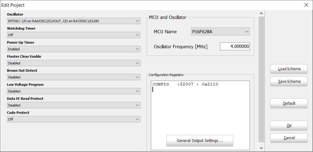
One of the most important points to take into account is the configuration of the oscillator, which is a subsystem in charge of generating the time base (clock) for the execution of instructions; with a frequency of 4MHz the time base (called instruction cycle) is 1 µs. Some instructions are executed in an instruction cycle, i.e. the microcontroller takes 1 µs to perform the instruction; therefore, the execution of the instructions is done at high speed. The PIC16F628A includes a 4MHz internal oscillator that is used when selecting INTOSC: I/O on RA6/OSC2, I/O on RA7/OSC1 for the Oscillator bit; the use of the internal oscillator is recommended as it makes it easier to assemble the electric circuit and frees two pins from the microcontroller, otherwise it would be necessary to add an external oscillator crystal with its associated elements.
The meaning and function of the other bits will become clearer as you delve deeper into your study of PIC microcontroller programming.
The text editor window will show, where we will write the source code of our project:
|
1 2 3 4 5 6 7 8 9 10 11 12 13 14 15 16 17 18 19 20 21 22 23 24 25 26 27 28 29 30 31 32 33 34 35 36 37 38 39 40 41 42 |
//Contador.c //Macros (equivalent symbols) #define BOTON RA4_bit //BOTON is equivalent to RA4_bit #define PRESIONADO 0 //PRESIONADO is equivalent to 0 //Function to convert from Binary to 7 segments char Bin2_7seg(char digit){ switch (digit){ case 0: return 0x3F; //0x3F is the 7-segment code of 0. case 1: return 0x06; //0x06 is the 7-segment code of 1. case 2: return 0x5B; case 3: return 0x4F; case 4: return 0x66; case 5: return 0x6D; case 6: return 0x7D; case 7: return 0x07; case 8: return 0x7F; case 9: return 0x67; } } //Variable declaration char contador=0; //The variable contador is of type char and has an initial value of 0. //Main function void main(){ PORTB=0x00; //Initial state of port B. CMCON=0x07; //Pins RA<3:0> as digital I/O. TRISB=0x00; //Port B as output. while (1){ if (BOTON==PRESIONADO){ //If pressed, Delay_ms(10); //wait 10ms, if (BOTON==PRESIONADO){ //check if the button is still pressed, while (BOTON==PRESIONADO); //and wait while it remains pressed. contador++; //When released, increment the contador, if (contador>9) contador=0; //and reset it to 0 if it exceeds the value of 9. } } PORTB=Bin2_7seg(contador); //Convert and send to port B the value //present in the variable contador. } }//End of the main function |
Once the writing is finished we proceed with the compilation (the translation of the previous code into machine code). This process is transparent to us (the only thing we will observe will be some messages during this phase at the bottom of the IDE). To compile we must select the Build > Build command. The machine code or executable code (identified as Contador.hex) is automatically saved in a file in the Contador folder that we created previously. The above code is an example that can be taken as a template for writing other projects. The PIC microcontroller executes the instructions that are within the main function void main(){...}, the remaining parts serve as supplementary code for the correct execution of those instructions. Macros are intended to facilitate the maintenance and understanding of the code; for example, if you want to use the RA7 pin instead of the RA4 pin, you simply have to type define BOTON RA7_bit; additionally BOTON==PRESIONADO it’s also much more comprehensible than RA4_bit==0.
A function is a grouping of instructions that are then treated as a new instruction within the main function; thus Bin2_7seg(contador); is considered as one more instruction and executed according to its definition. In mikroC (as well as in other programming languages) it is mandatory to declare the variables used in the main function, indicating their type and optionally their initial value; thus char contador=0; is the declaration of the variable contador as a variable of type character (it can take values between 0 and 255) and has in this case an initial value of 0.
The Contador.hex machine code has to be written in the program memory of the PIC microcontroller in such a way that when it is turned on it executes the instructions indicated, otherwise the PIC microcontroller would be a useless device since its program memory is blank when it leaves the factory. The programming process is done by means of a programmer.
The last step is to assemble the electrical circuit of the counter, keeping in mind that the power supply must be 5V (this voltage can be easily obtained from a 7805 regulator).

As an important recommendation, it is suggested to add a 0.1uF ceramic capacitor between the power pins of the PIC (VDD-VSS), which will help eliminate potential problems caused by rapid fluctuations in the power supply. Also, note that the connection to the display is direct (no resistors in between), which is possible because PIC microcontrollers are designed to supply a maximum current of 25mA in each of their pins. When the circuit is turned on, it will be observed that the display shows the number 0 since this is how the PIC was programmed. If the push button is pressed (and released) the count will be increased by one unit to a maximum count of 9, on the next press the count will return to 0.
To learn more about PIC microcontroller programming, you can purchase the e-book that contains the most detailed theoretical foundation and many meticulously explained real examples, as well as the simulations in Proteus so that you can verify its operation quickly and effectively.
Examples of PIC programming in mikroC
PIC to PIC communication
Wired communication between PIC microcontrollers is of utmost importance because it allows you to have systems with multiple microcontrollers executing different tasks in a coordinated manner. Data transmission can be achieved bi-directionally using the built-in USART module or mikroC functions.
Communication between two microcontrollers PIC16F628A using mikroC’s USART-Software module is described.
It consists of two projects, one for each PIC:
- The PIC_a_PIC_LCD project is used to receive data and present it on a 2×16 LCD.
- The PIC_a_PIC project is used to send data.
First source code
|
1 2 3 4 5 6 7 8 9 10 11 12 13 14 15 16 17 18 19 20 21 22 23 24 25 26 27 28 29 30 31 32 33 34 35 36 37 38 39 40 41 42 43 44 45 46 47 48 49 50 |
//PIC_a_PIC_LCD.c //Microcontroller: PIC16F628A //Oscillator: Internal-4MHz //This program is stored in one of the two microcontrollers (U2) and continuously receives a //data (the letter 'r') every 300 ms by the reception pin RB6(12). The transmission pin is //RB7(13). The received data is displayed on the LCD. //The transmission speed of 600 Bauds was selected experimentally by a //trial and error procedure. The pin RB0(6) lights up for 1 second in case of //trying to establish a very high or very low transmission speed. //Declaration of the 12 variables necessary for the connection of the LCD module. sbit LCD_RS at RA4_bit; sbit LCD_EN at RA6_bit; sbit LCD_D4 at RA0_bit; sbit LCD_D5 at RA1_bit; sbit LCD_D6 at RA2_bit; sbit LCD_D7 at RA3_bit; sbit LCD_RS_Direction at TRISA4_bit; sbit LCD_EN_Direction at TRISA6_bit; sbit LCD_D4_Direction at TRISA0_bit; sbit LCD_D5_Direction at TRISA1_bit; sbit LCD_D6_Direction at TRISA2_bit; sbit LCD_D7_Direction at TRISA3_bit; // End of variable declaration. char error, byte_read; void main(){ CMCON=0x07; //Pins RA<3:0> as digital I/O. PORTB=0x00; TRISB0_bit=0; Lcd_Init(); //Initializes the LCD. Lcd_Cmd(_LCD_CLEAR); //Clears the display. Lcd_Cmd(_LCD_CURSOR_OFF); //Turns off the cursor. error = Soft_UART_Init(&PORTB, 6, 7, 600, 0); //Initializes the UART-Software module at 600 Bauds. if (error >0){ RB0_bit=1; Delay_ms(1000); RB0_bit=0; while(1); //Stops the program in case of error. } Delay_ms(100); while(1) { byte_read = Soft_UART_Read(&error); //Receives a data and saves it in byte_read. if (!error) //If there is no error. Lcd_Chr_CP(byte_read); //Sends the received data to the LCD. Delay_ms(200); } } |
Second source code
|
1 2 3 4 5 6 7 8 9 10 11 12 13 14 15 16 17 18 19 20 21 22 23 24 25 26 27 28 29 |
//PIC_a_PIC.c //Microcontroller: PIC16F628A //Oscillator: Internal-4MHz //This program is stored in one of the two microcontrollers (U1) and continuously transmits a //data (the letter 'r') every 300 ms by the transmission pin RB6(12). The reception pin is //RB7(13). //The transmission speed of 600 Bauds was selected experimentally by a //trial and error procedure. The pin RB0(6) lights up for 1 second in case of //trying to establish a very high or very low transmission speed. char error; void main(){ CMCON=0x07; //Pins RA<3:0> as digital I/O. PORTB=0x00; TRISB0_bit=0; error = Soft_UART_Init(&PORTB, 7, 6, 600, 0); //Initializes the UART-Software module at 600 Bauds. if (error >0){ RB0_bit=1; Delay_ms(1000); RB0_bit=0; while(1); //Stops the program in case of error. } Delay_ms(100); while (1){ Soft_UART_Write('r'); //Sends the character 'r' every 300 ms. Delay_ms(300); } } |
Electric Circuit Diagram

MT8870 DTMF Decoder with PIC16F628A
The MT8870 DTMF decoder operates in conjunction with a PIC16F628A configured to work with its internal 4MHz oscillator. An interruption due to Timer0 is generated every 50ms (0.050 seconds) which is taken as a time base to account for the different intervals necessary for the operation of the circuit.
For this example, the purpose is to activate and deactivate pin RB0 (6) using a password entered through the phone keypad. The activation password is 1973, the deactivation password is 1974. If the circuit is turned off for any reason, turning it on again restores the last state that the pin RB0 had.
Additionally, when entering the password 3579, RB1 pin (7) is activated for 10 seconds. When entering the digits the PIC waits 3 seconds. If a new digit is not entered, the PIC performs the corresponding task. If less or more than 4 digits are entered, the PIC does not take any action. To enter a new password you simply have to wait more than 3 seconds. Every 12 hours RB2 pin (8) is turned on for a period of 1 hour.
To check the correct operation of the MT8870, a very simple circuit can be built as indicated in the Tester for the MT8870, below in the Additional Information.
Source code in mikroC
|
1 2 3 4 5 6 7 8 9 10 11 12 13 14 15 16 17 18 19 20 21 22 23 24 25 26 27 28 29 30 31 32 33 34 35 36 37 38 39 40 41 42 43 44 45 46 47 48 49 50 51 52 53 54 55 56 57 58 59 60 61 62 63 64 65 66 67 68 69 70 71 72 73 74 75 76 77 78 79 80 81 |
//DTMF.c //Microcontroller: PIC16F628A. //Internal oscillator: 4MHz char tecla[12], i=0, j, num_cifras, conteo=0, m=0, estado=0, pin=0, p=0; int k=0, n=0; //Main function. void main(){ PORTB=0x00; //Initialization. CMCON=0x07; //Pins RA<3:0> as digital I/O. TRISB=0x00; //Port B as output. OPTION_REG=0b11010111; //Timer0 as timer. Prescaler assigned //to Timer0. Prescaler 1:256. GIE_bit=1; //Interrupts enabled. T0IE_bit=1; //Timer0 interrupt enabled. RB0_bit=EEPROM_Read(0x00); //Updates the pin RB0 to its last state. //The first time the PIC is turned on, the state of //pin RB0 will be 1. TMR0=61; //Initial value of TMR0 (interrupt every 50ms). while (1){ while (RA4_bit==0) ; //Wait while there is no data available. while (RA4_bit==1) ; //Data available. Wait while RA4 is high. i++; estado=1; num_cifras=i; tecla[i]=PORTA; //Reads the available data and stores it. conteo=0; } } void interrupt(void){ TMR0=61; //Initial value of TMR0. conteo++; if (conteo==60 && estado==1){ if (tecla[1]==1 && tecla[2]==9 && tecla[3]==7 && tecla[4]==3 && num_cifras==4){ //Password:1973 RB0_bit=1; //Activates the pin RB0. EEPROM_Write(0x00,1); //Saves the state of the pin RB0. } if (tecla[1]==1 && tecla[2]==9 && tecla[3]==7 && tecla[4]==4 && num_cifras==4){ //Password:1974 RB0_bit=0; //Deactivates the pin RB0. EEPROM_Write(0x00,0); //Saves the state of the pin RB0. } if (tecla[1]==3 && tecla[2]==5 && tecla[3]==7 && tecla[4]==9 && num_cifras==4){ //Password:3579 RB1_bit=1; //Activates the pin RB1. for (j=1;j<=10;j++) //Waits 10 seconds. Delay_1sec(); RB1_bit=0; //Deactivates the pin RB1. } i=0; conteo=0; estado=0; } if (conteo==60) //Resets the variable conteo if no key has been pressed conteo=0; //in 3 seconds. k++; if (k==28800){ //Counts 12 hours (28.800x30x0,050 seconds). k=0; m++; if (m==30){ m=0; RB2_bit=1; //Turns on the pin RB2. pin=1; //Records the turning on of RB2. } } if (pin==1){ //Counts 1 hour if RB2 is on. n++; if (n==14400){ //Counts 1 hour (14.400x5x0,050 seconds). n=0; p++; if (p==5){ p=0; RB2_bit=0; //Turns off the pin RB2 after 1 hour. pin=0; } } } T0IF_bit=0; //Clears the interrupt flag. } |
Electric Circuit Diagram

Additional information
DTMF telephone dialer with PIC16F628A
The example shown attempts to describe only the basic process of generating calls with the PIC16F628A microcontroller and the W91314A IC.
The DTMF W91314A telephone dialer from Windbond Electronics is a monolithic integrated circuit that provides the signals needed for pulse or tone dialing. The integrated circuit W91314A has a redial memory.
Characteristics of the W91314A integrated circuit
- Telephone dial switchable between DTMF tones or pulses
- 32 digits for redial memory
- Pulse-to-Tone key (P -> T) for long-distance call operation
- Can use a 4×4 keyboard or electronic control of a microcontroller
- Easy operation with redial, flash, pause and P->T keys
- The functions of Flash, Pause, P-> T (pulse-to-tones) can be stored as a digit in memory
- Minimum output tone duration: 100 ms
- Minimum pause between tones: 100 ms
- On-chip power-up reset
- Uses a 3.579545 MHz ceramic crystal or resonator
- Packaged in 18-pin plastic DIP
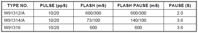
The different dialers in the W91310 series are shown in the table below:
Pinout

R<4:1> – C<4:1> Row-Column
The Keyboard input can be either from the standard 4×4 keyboard or a simple, low-cost, single-touch keyboard. Electronic input can also be used from a microcontroller. A valid keyboard input is defined as a single row connected to a single column.
XT, /XT
Crystal or 3.579545 MHz ceramic resonator.
MODE (Input)
Connecting the MODE pin to Vss puts the chip into Tone mode. Connecting the MODE pin to VDD puts the W91314A into Pulse mode (10 pps). Leaving the pin unplugged puts the W91314A in Pulse mode (20 pps).
/HKS (Hang switch input)
/HKS = 1: Hang Up Status. Chip in sleep mode, no operation.
/HKS = 0: Off the hook status. Chip enabled for normal operation.
The /HKS pin is connected to VDD by an internal resistor.
DTMF (Output)

In Pulse mode, it remains in a low state at all times. In Tone mode, this output emits a double or single tone.
VDD, Vss
Power Pins
B/M (Input)
This pin serves no function in Tone mode.
Keyboard Operation

To generate a call, simply put the telephone dialer W91314A in the Off the hook mode (/HKS = 0) and then press the keys corresponding to the desired phone number. Connecting a row (R) to a column (C) simultaneously generates the two tones indicated in the table above, which are sent by the DTMF pin.
Operation with PIC16F628A
If you use a PIC16F628A microcontroller to replace the keyboard, the basic idea is the same: if you want to generate a call, you must put the W91314A in Off Hook mode and then connect the rows and columns according to each digit you want to dial. The technique consists of attaching the 8 R<4:1> – C<4:1> pins of the W91314A to the 8 pins of the microcontroller (momentarily configured as outputs) and then sending low levels (GND) to the two pins of the PIC that are attached to the two pins of the W91314A that want to be joined. For example, to dial the digit “8”, the 2 pins of the PIC connected to C2 and R3 must be set to a low level; in this way, the C2 and R3 pins are connected to GND, which is equivalent to a direct C2 – R3 junction. In the following circuit you can see the details:

Example with PIC16F628A
In the following code it should be noted that originally the pins of the PIC16F628A microcontroller are configured as inputs (by default) which makes them present a high impedance (Z) state. Pin pairs are momentarily configured as outputs to send the low level (GND) and then reset to their initial high-impedance setting. Otherwise, unwanted interconnections of the W91314A pins would occur.
DiscadorDTMF.c: Generates a call to the 0987438877 number using the W91314A circuit as the DTMF generator and the PIC16F628A as the electronic keypad. The dial is in Off Hook mode as the pin /HKS is connected to GND (0).
|
1 2 3 4 5 6 7 8 9 10 11 12 13 14 15 16 17 18 19 20 21 22 23 24 25 26 27 28 29 30 31 32 33 34 35 36 37 38 39 40 41 42 43 44 45 46 47 48 49 50 51 52 53 54 55 56 57 58 59 60 61 62 63 64 65 66 67 68 69 70 71 72 73 74 75 76 77 78 79 80 81 82 83 84 85 86 87 88 89 90 91 92 93 94 95 96 97 98 99 100 101 |
//DiscadorDTMF.c //Microcontroller: PIC16F628A //Internal oscillator: 4MHz (TCI=1us) #define R4 RB7_bit #define R3 RB6_bit #define R2 RB5_bit #define R1 RB4_bit #define R4D TRISB7_bit #define R3D TRISB6_bit #define R2D TRISB5_bit #define R1D TRISB4_bit #define C4 RA3_bit #define C3 RA2_bit #define C2 RA1_bit #define C1 RA0_bit #define C4D TRISA3_bit #define C3D TRISA2_bit #define C2D TRISA1_bit #define C1D TRISA0_bit void main(){ CMCON=0x07; //Pins RA as digital I/O. TRISA=0xFF; //Port A as input. TRISB=0xFF; //Port B as output. Delay_ms (2000); //Wait 2 seconds before making the call. //0 C2=0; R4=0; //Write low levels in the output latch. C2D=0; R4D=0; //Send the low levels to the output pins. Delay_ms(80); //Generate the tones for 80 ms. C2D=1; R4D=1; //Reset the pins to their high Z state. Delay_ms(200); //Wait 200ms before sending the next digit. //9 C3=0; R3=0; C3D=0; R3D=0; Delay_ms(80); C3D=1; R3D=1; Delay_ms(200); //8 C2=0; R3=0; C2D=0; R3D=0; Delay_ms(80); C2D=1; R3D=1; Delay_ms(200); //7 C1=0; R3=0; C1D=0; R3D=0; Delay_ms(80); C1D=1; R3D=1; Delay_ms(200); //4 C1=0; R2=0; C1D=0; R2D=0; Delay_ms(80); C1D=1; R2D=1; Delay_ms(200); //3 C3=0; R1=0; C3D=0; R1D=0; Delay_ms(80); C3D=1; R1D=1; Delay_ms(200); //8 C2=0; R3=0; C2D=0; R3D=0; Delay_ms(80); C2D=1; R3D=1; Delay_ms(200); //8 C2=0; R3=0; C2D=0; R3D=0; Delay_ms(80); C2D=1; R3D=1; Delay_ms(200); //7 C1=0; R3=0; C1D=0; R3D=0; Delay_ms(80); C1D=1; R3D=1; Delay_ms(200); //7 C1=0; R3=0; C1D=0; R3D=0; Delay_ms(80); C1D=1; R3D=1; Delay_ms(200); } |
The example shown attempts to describe only the basic process of generating calls with the PIC16F628A microcontroller and the W91314A IC. It can be improved so that the line connection is automated as well as the Off Hook status. Other options can also be added according to the reader’s liking, such as calling multiple phone numbers, generating calls triggered by one or more sensors, transmitting recorded voice messages, etc.
POV Display
The POV (Persistence Of Vision) display operates based on the persistence of human vision when an object moves quickly; the rotation of a LED column that light up in a certain sequence causes an image to form in the observer’s mind that depends on the code programmed into a PIC microcontroller.
The POV display consists of a PIC16F88, an adjustable voltage regulator ECG1900 for the PIC (to control the current flowing through the LEDs), a column of 7 RGB LEDs and a 5VDC motor with voltage variation speed control using LM317T regulator. For each letter the PIC sequentially sends 5 groups of 7 bits, either to port A (green) or port B (red). Due to the counterclockwise rotation of the LED column and the phenomenon of persistence of vision, the corresponding image is formed in the mind of the observer. The PIC can be programmed with different sequences to present a wide variety of messages. Below is an example of how to create text with the POV display, when you put it into operation you will see the word “microC“
Source code in mikroC
|
1 2 3 4 5 6 7 8 9 10 11 12 13 14 15 16 17 18 19 20 21 22 23 24 25 26 27 28 29 30 31 32 33 34 35 36 37 38 39 40 41 |
//POV.c void main(){ OSCCON=0x70; //Internal oscillator at 8MHz (TCI=0.5 us). PORTA=0x00; //Initialization. PORTB=0x00; ANSEL=0x00; //AN pins as digital I/O. TRISA=0x00; //Port A as output. TRISB=0x00; //Port B as output. PORTB=0x7E;Delay_us(500); //m PORTB=0x02;Delay_us(900); PORTB=0x7E;Delay_us(500); PORTB=0x02;Delay_us(900); PORTB=0x7C;Delay_us(500); PORTB=0x00;Delay_us(1500); PORTA=0xDA;Delay_us(500); //i PORTA=0x00;Delay_us(1500); PORTB=0x3C;Delay_us(500); //c PORTB=0x42;Delay_us(1500); PORTB=0x24;Delay_us(500); PORTB=0x00;Delay_us(1500); PORTA=0xDE;Delay_us(500); //r PORTA=0x04;Delay_us(500); PORTA=0x02;Delay_us(1000); PORTA=0x04;Delay_us(500); PORTA=0x00;Delay_us(1500); PORTB=0x3C;Delay_us(500); //o PORTB=0x42;Delay_us(1500); PORTB=0x3C;Delay_us(500); PORTB=0x00;Delay_us(1500); PORTA=0x5E;Delay_us(500); //C PORTA=0x81;Delay_us(1500); PORTA=0x42;Delay_us(500); PORTA=0x00; } |
Electric Circuit Diagram

Additional information
- C Language Basics (for Computers)
- Introductory C Language Course (for computers)
- Microchip’s Mid-Range Microcontroller Reference Manual